Multi-Axis Linear Motion Systems
Compare 16 standard mechanical configurations by architecture, controlled axes and drive technology. Open a model page for verified axis data and configuration review.
Cantilever Systems
Open-sided XY and XYZ layouts for side access and space-conscious automation cells.
2-Axis Models
XY controlled motion
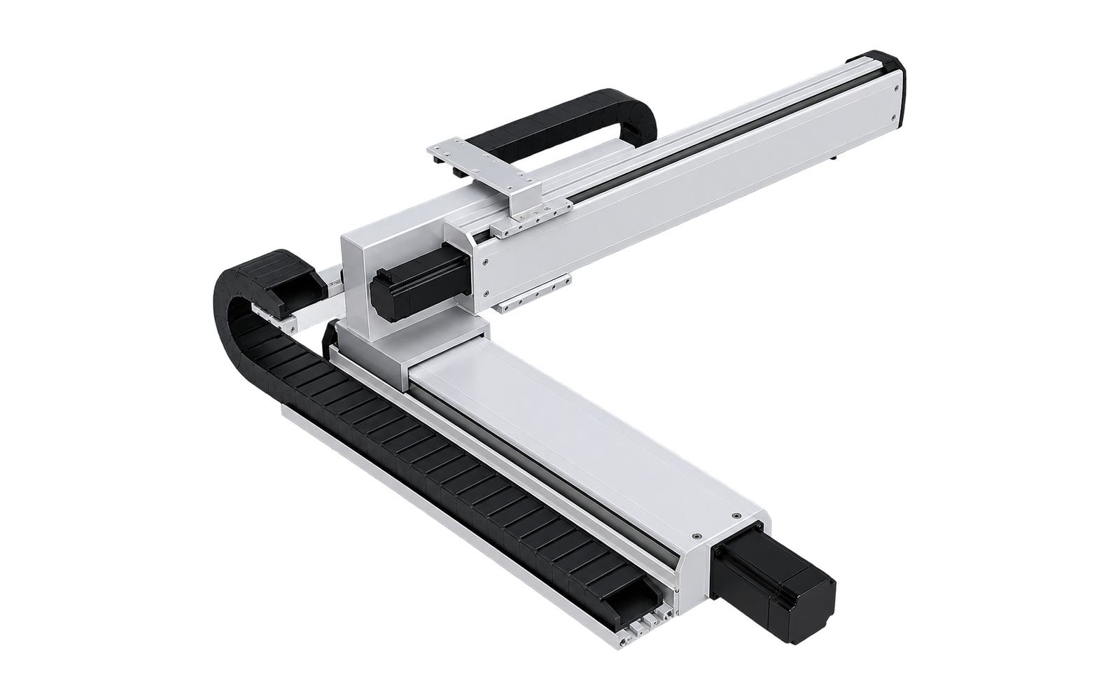
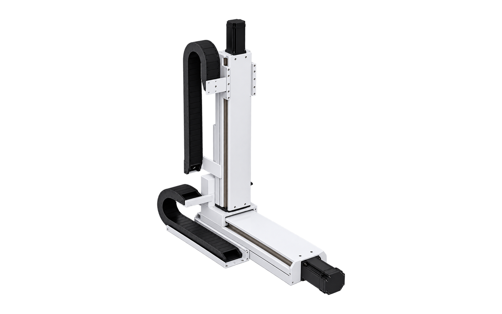
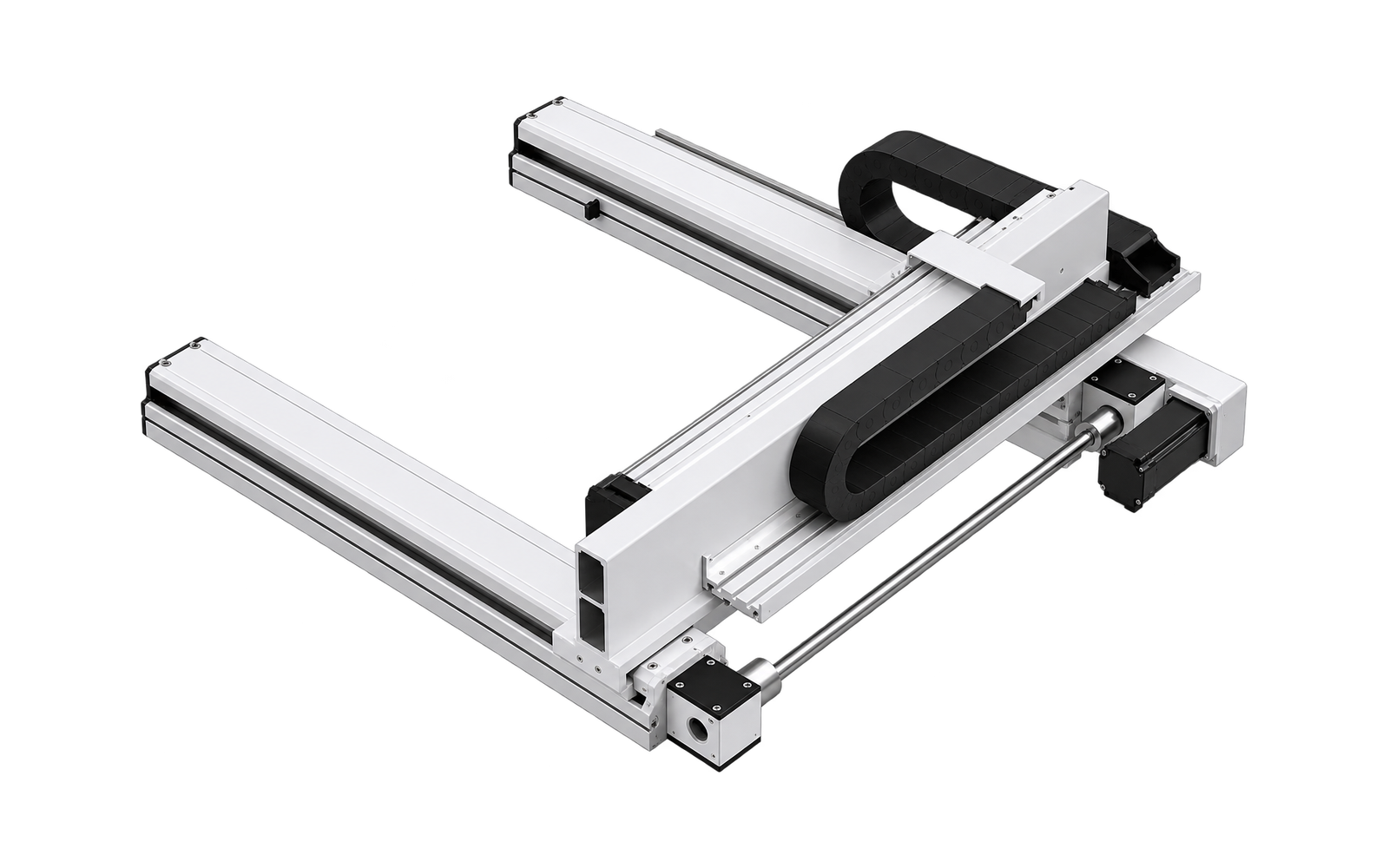
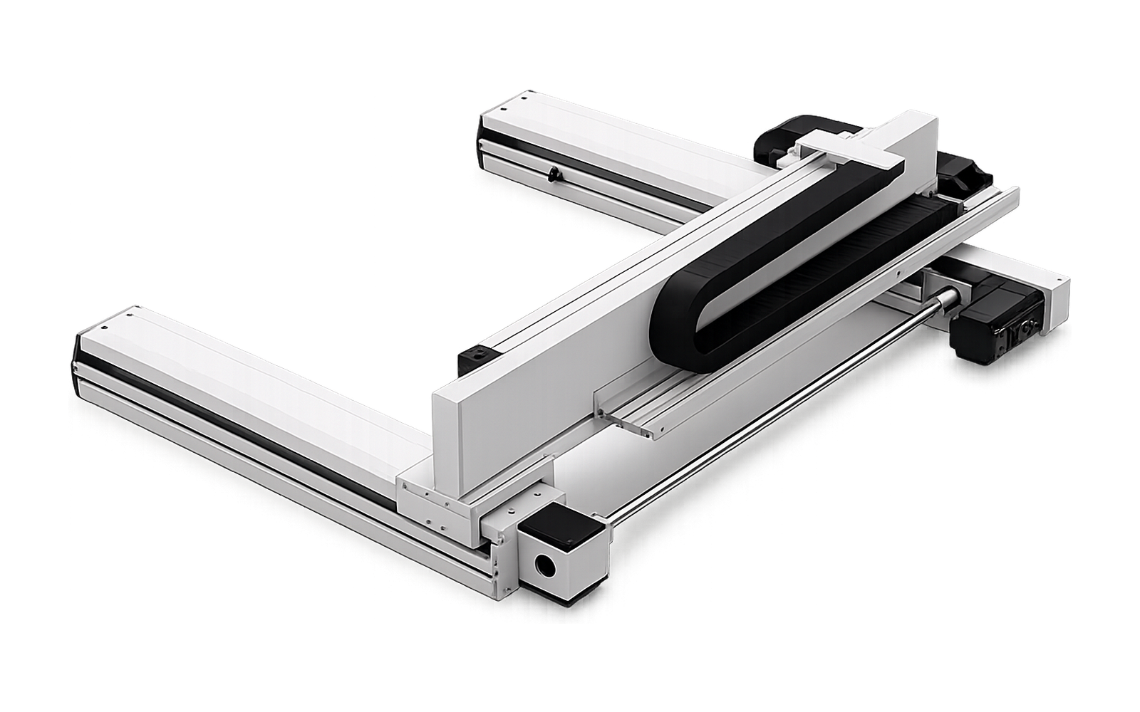
Cantilever XY Ball-Screw System
Ball-screw actuator configuration
MX-CT2-BS-01
3-Axis Models
XYZ controlled motion
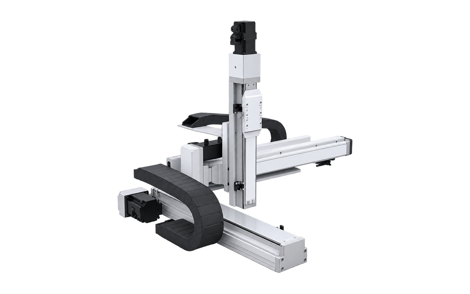
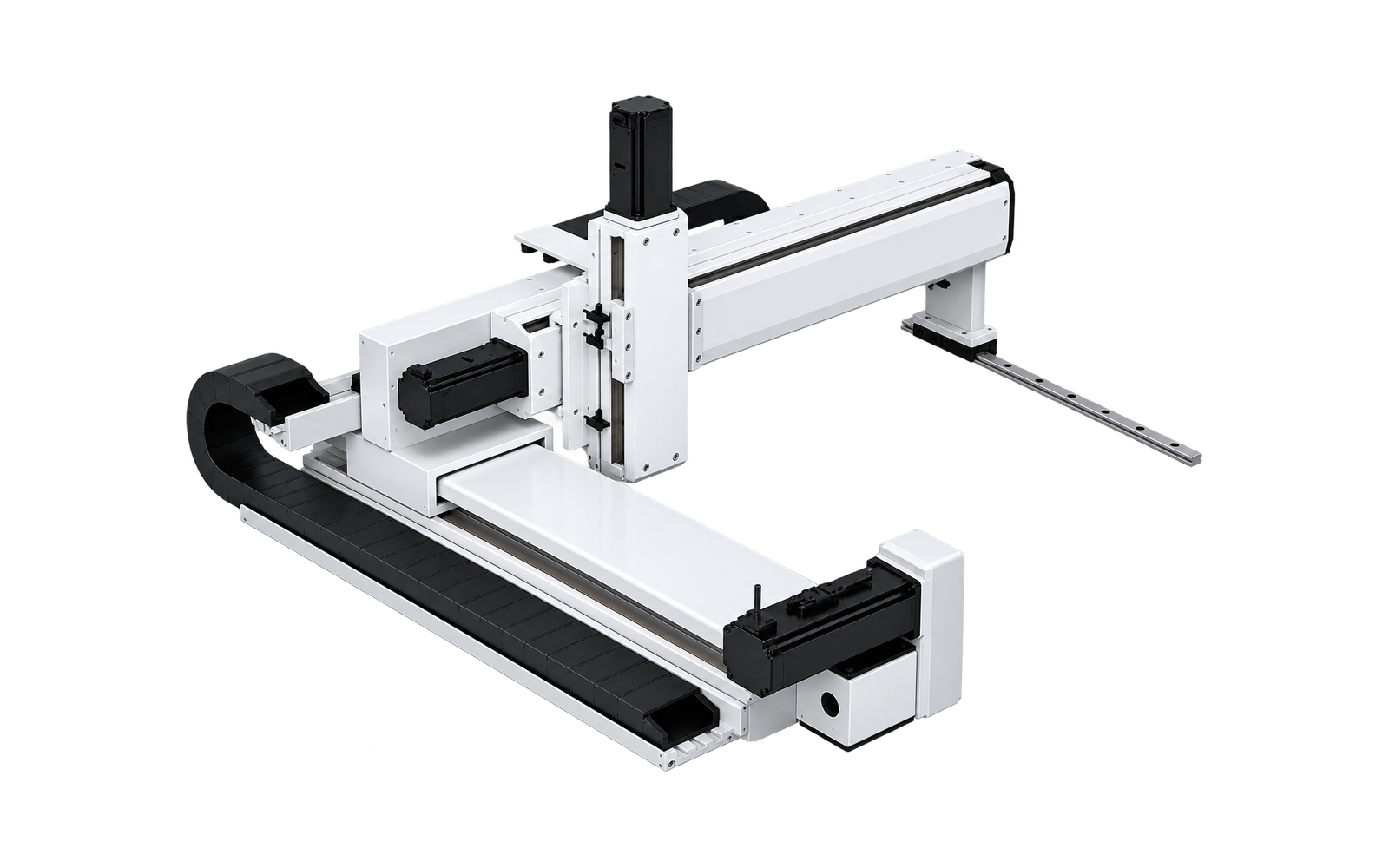
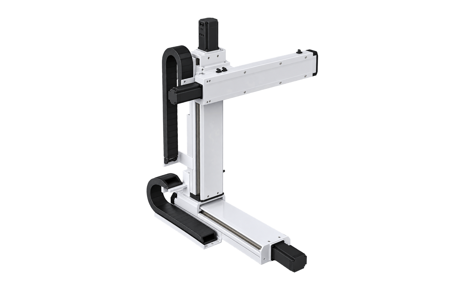
Cantilever XYZ Ball-Screw System
Embedded ball-screw actuator configuration
MX-CT3-IB-01
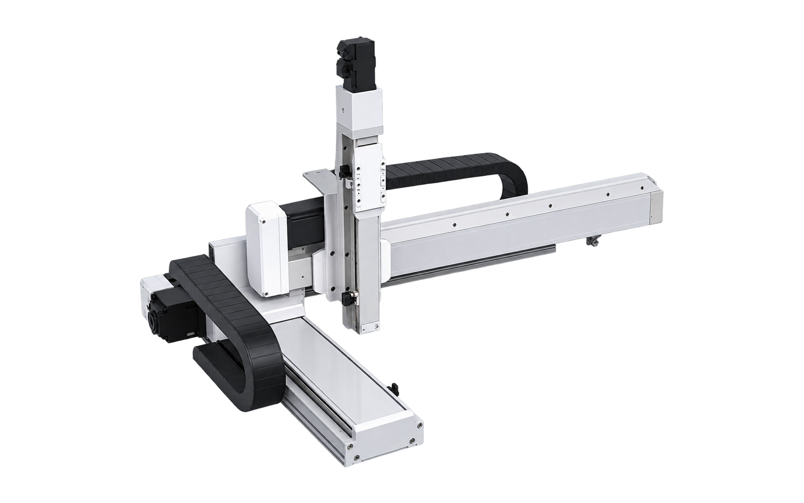
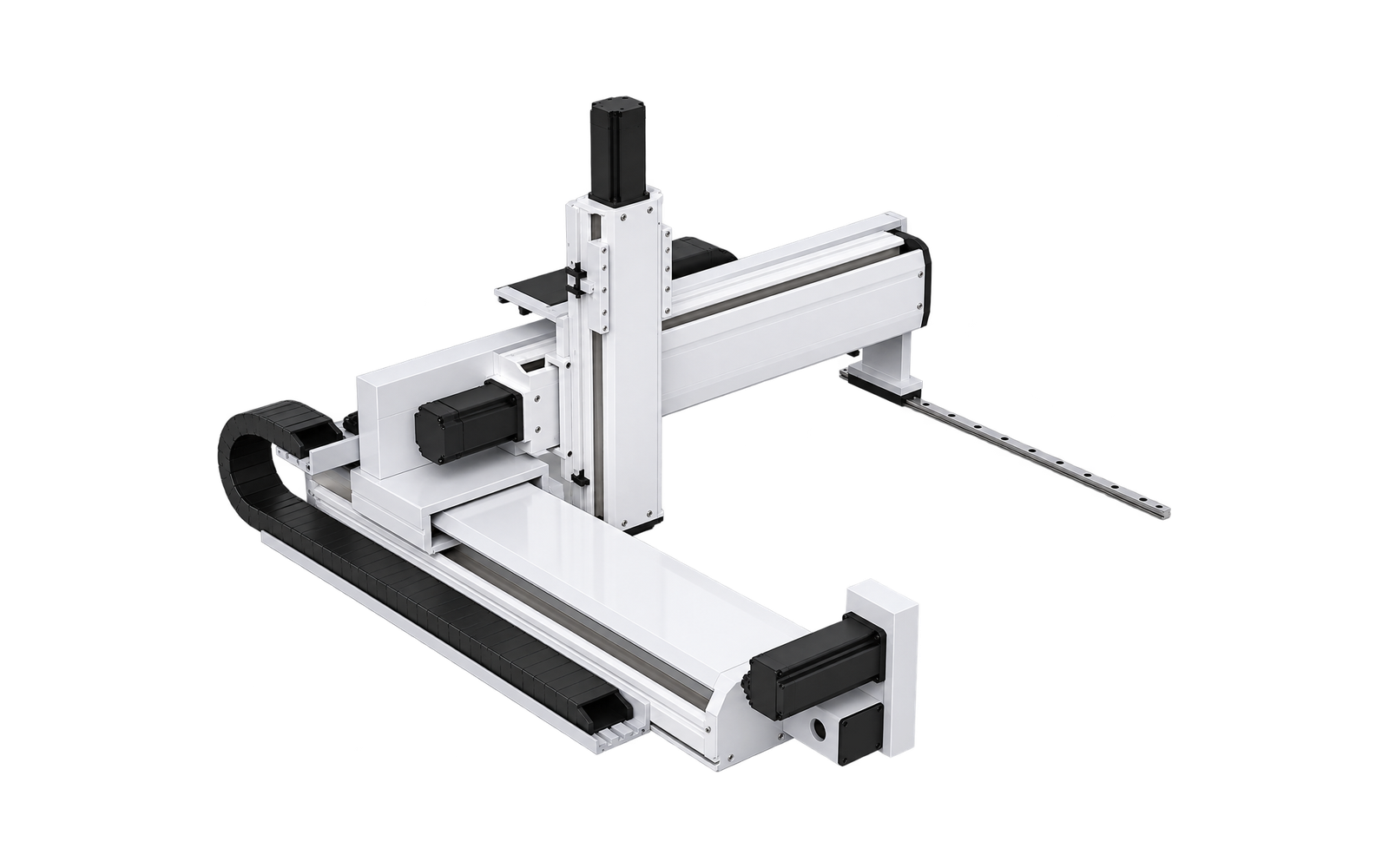
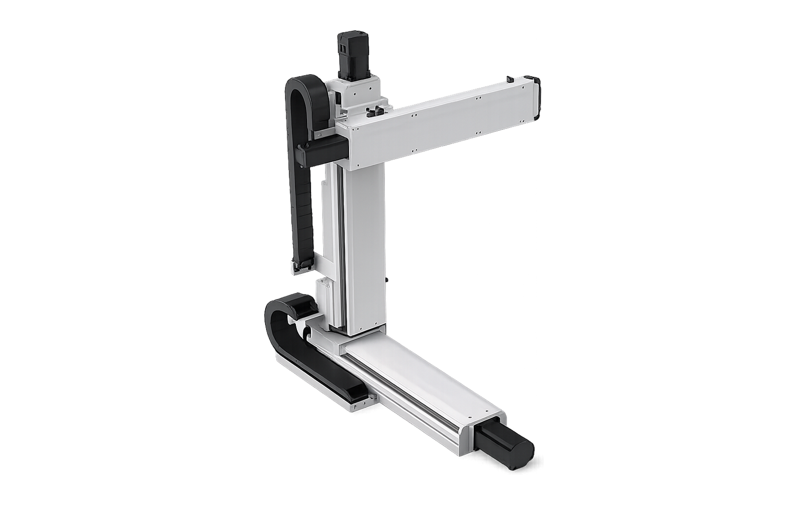
Cantilever XYZ Ball-Screw System
Embedded ball-screw actuator configuration
MX-CT3-IB-02
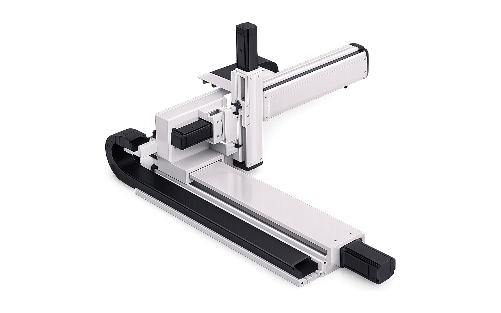
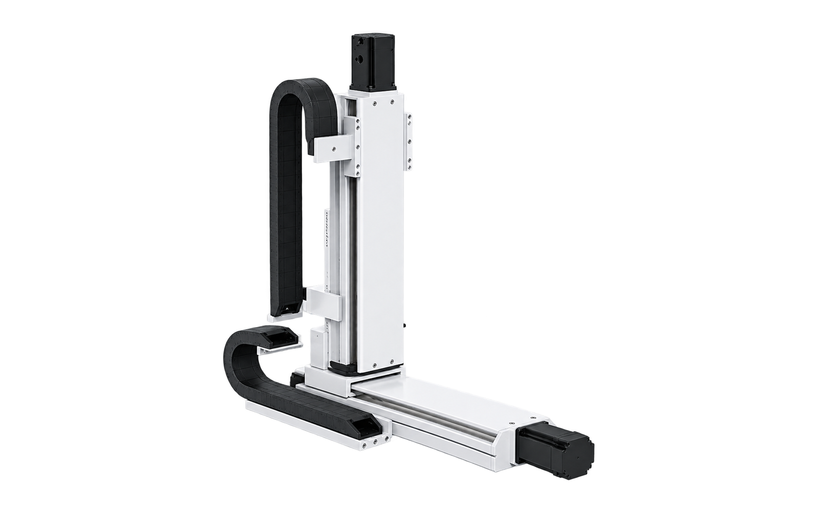
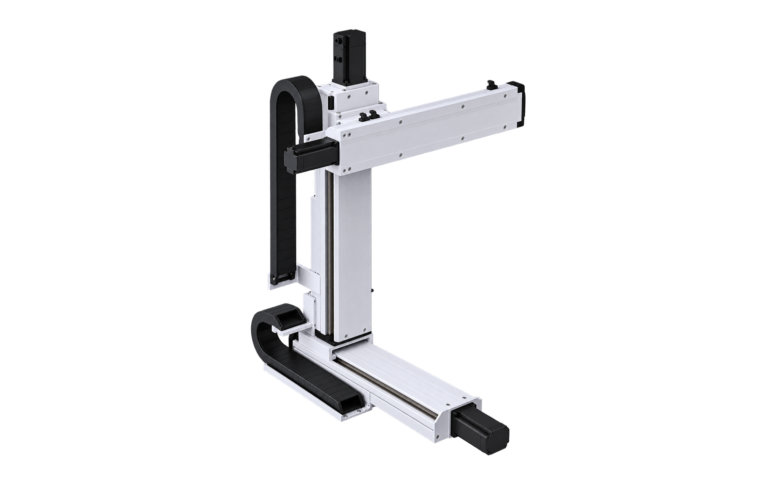
Cantilever XYZ Ball-Screw System
Standard ball-screw actuator configuration
MX-CT3-BS-01
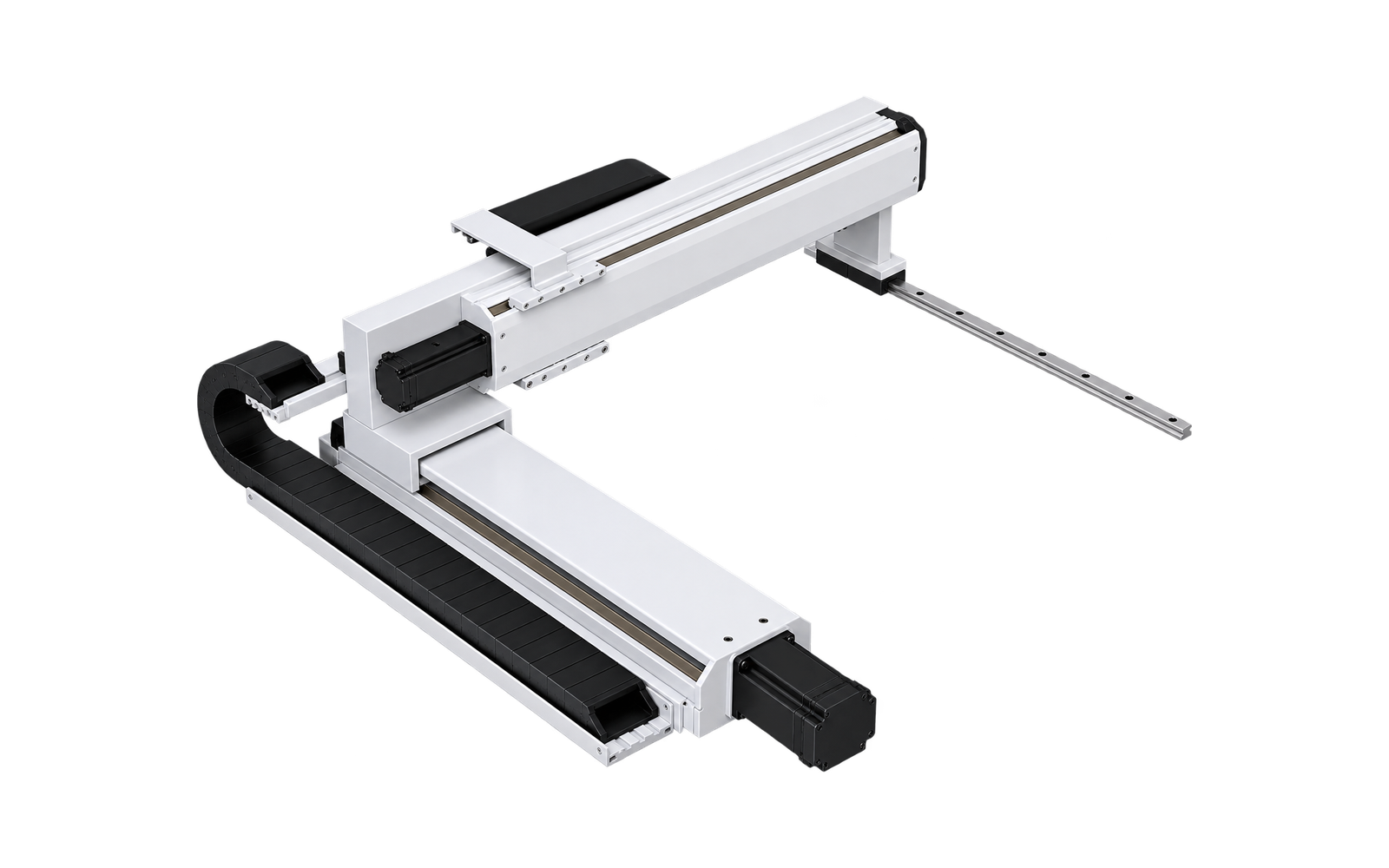
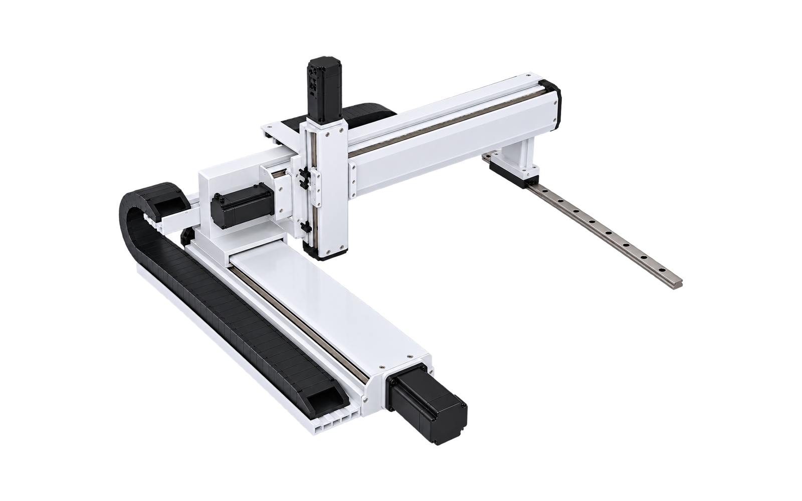
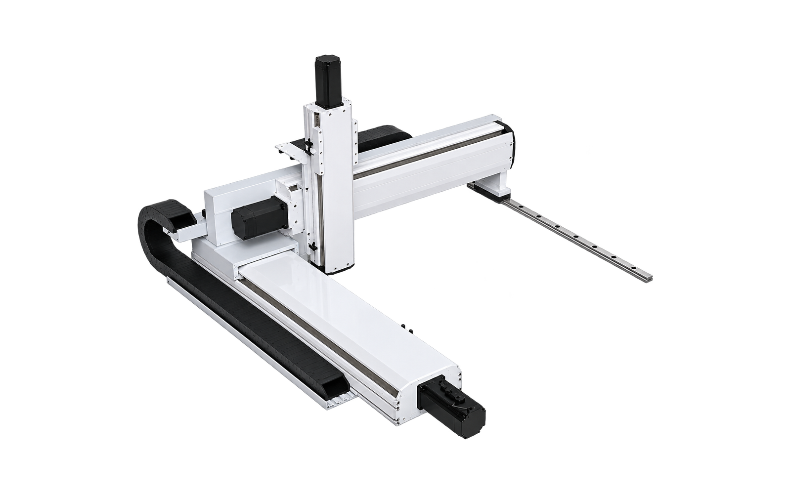
How to read the HS LINEAR model code
The base model identifies a stable mechanical configuration. The drive field now uses one consistent dimension: BS for Ball Screw and HB for Hybrid: Belt + Ball Screw. Embedded construction is shown separately as a product feature.
Need help selecting a multi-axis model?
Send required strokes, moving load, load center, speed, cycle time, mounting orientation, motor preference and end tooling. HS LINEAR will review the architecture and configuration boundary.
* Reference payloads are preliminary catalog maxima and may vary with carried-axis stroke, tooling geometry, center of gravity, acceleration, mounting and duty cycle. Final selection requires engineering review and an approved drawing.
“2-axis” and “3-axis” describe controlled Cartesian axes. Dual-X Gantry has two controlled axes but uses three linear actuators because the two X actuators move synchronously.


