X
Ball-screw driveX axis · BSFE120
Long-travel base axis
- Standard selectable travel
- 50–1100 mm
- Ball-screw lead
- 20 mm
- Maximum speed
- Up to 1000 mm/s
- Axis repeatability
- ±0.01 mm
- Motor reference
- 400 W
A 3-axis positioning platform with clearly defined X, Y and Z motion roles. Select travel, motor-side orientation, motion package and delivery scope for an engineering quotation.
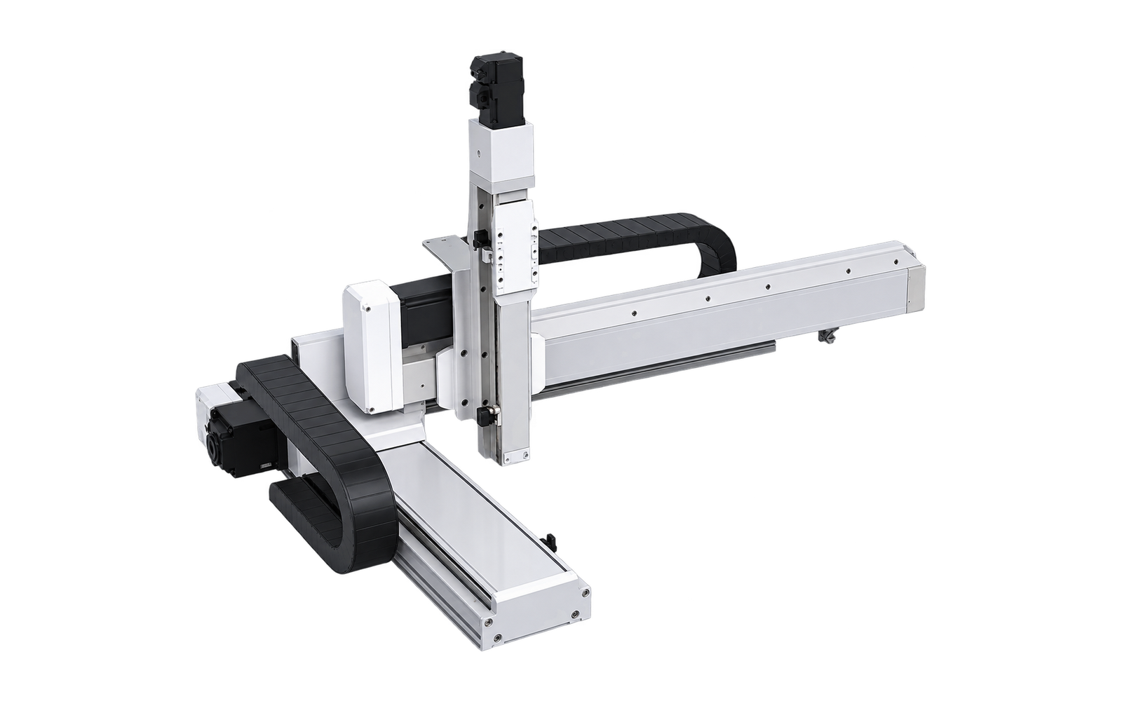
The axis families and drive principles are fixed for this platform. Travel and project options are selected below.
Long-travel base axis
Cross-travel axis
Vertical process axis
Use the table and live summary together. Final suitability also depends on load center, acceleration and duty cycle.
The current travel combination is highlighted.
| Y \ Z (mm) | 50 | 100 | 150 | 200 | 250 | 300 | 350 |
|---|---|---|---|---|---|---|---|
| 100 | 10 | 10 | 10 | 10 | 10 | 10 | 10 |
| 150 | 10 | 10 | 10 | 10 | 10 | 10 | 10 |
| 200 | 10 | 10 | 10 | 10 | 10 | 10 | 10 |
| 250 | 10 | 10 | 10 | 10 | 10 | 10 | 10 |
| 300 | 10 | 10 | 10 | 10 | 10 | 10 | 10 |
| 350 | 10 | 10 | 10 | 10 | 10 | 10 | 10 |
| 400 | 10 | 10 | 10 | 10 | 10 | 10 | 10 |
| 450 | 8 | 7.7 | 7.4 | 7.1 | 6.9 | 6.7 | 6.5 |
| 500 | 5 | 4.7 | 4.4 | 4.1 | 3.9 | 3.7 | 3.5 |
Record the information needed for quotation discussion. This reference is not a final product designation.
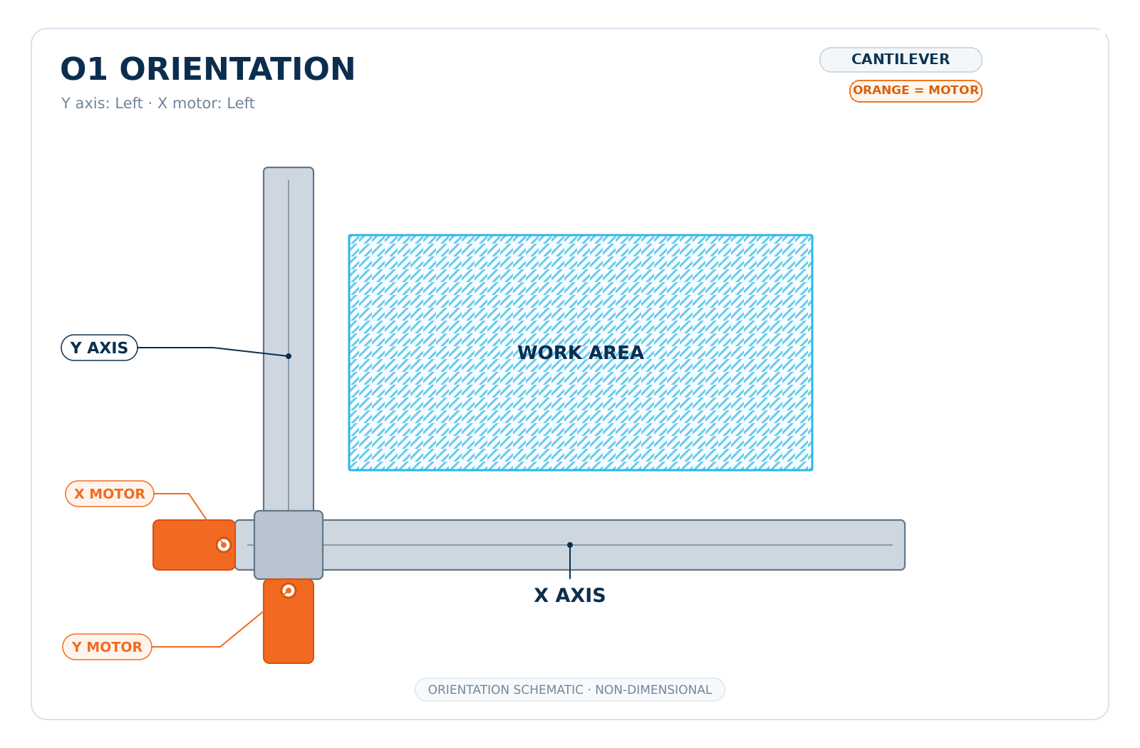
The direction schematic identifies the arrangement; the full-width engineering drawing carries the dimensional detail.
Direction-identification schematic. Use the drawing below for dimensions.
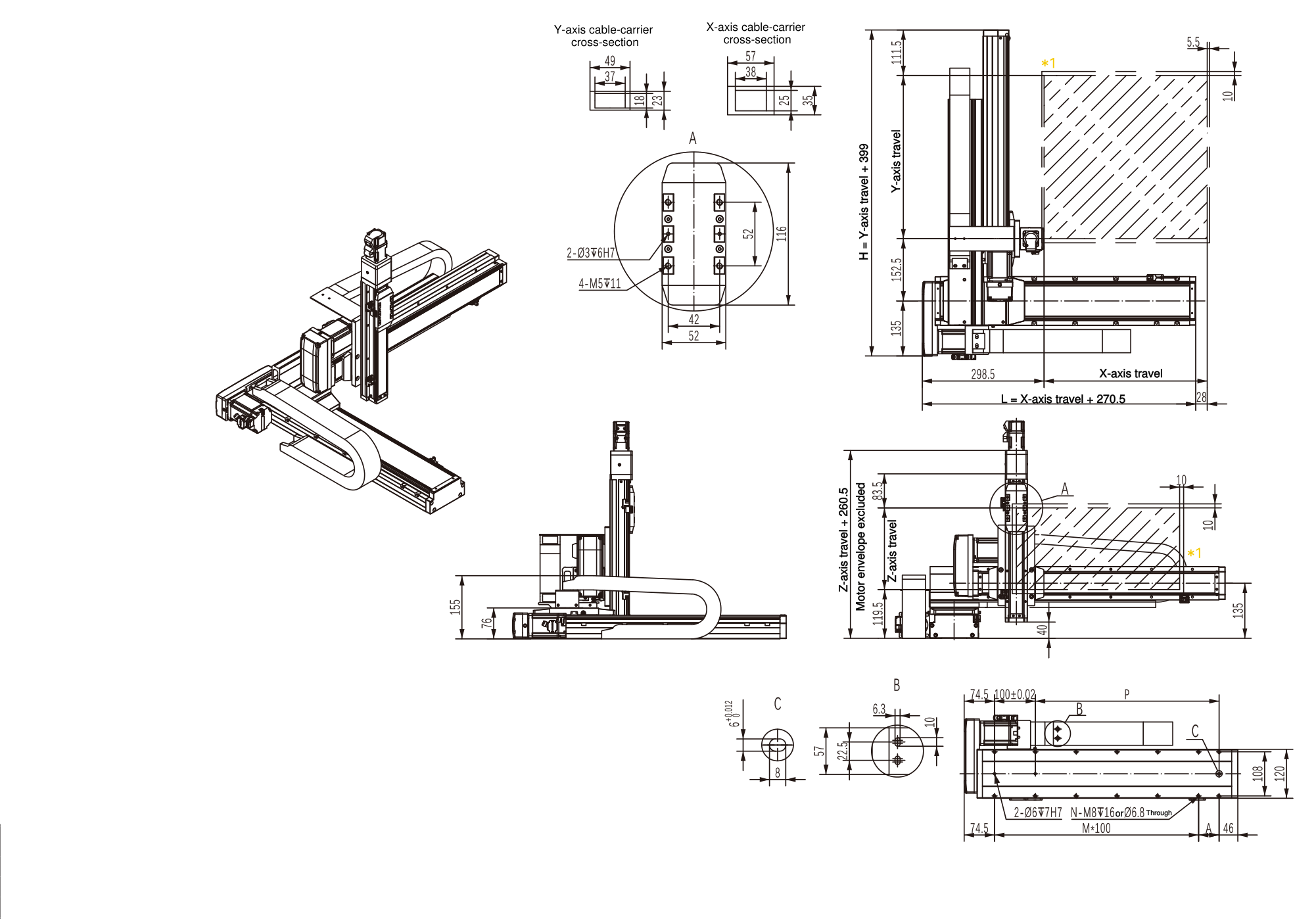
Lettered dimensions correspond to the callouts on the full-width engineering drawing; M = number of the stated mounting-pitch intervals; N = number of mounting holes in the axis mounting pattern.
X travel 1150–1250 mm is retained in the complete dimension table for reference only. It is not a standard selection and requires engineering review.
| X travel (mm) | 50 | 100 | 150 | 200 | 250 | 300 | 350 | 400 | 450 | 500 | 550 | 600 | 650 | 700 | 750 | 800 | 850 | 900 | 950 | 1000 | 1050 | 1100 | 1150 | 1200 | 1250 |
|---|---|---|---|---|---|---|---|---|---|---|---|---|---|---|---|---|---|---|---|---|---|---|---|---|---|
| L (mm) | 320.5 | 370.5 | 420.5 | 470.5 | 520.5 | 570.5 | 620.5 | 670.5 | 720.5 | 770.5 | 820.5 | 870.5 | 920.5 | 970.5 | 1020.5 | 1070.5 | 1120.5 | 1170.5 | 1220.5 | 1270.5 | 1320.5 | 1370.5 | 1420.5 | 1470.5 | 1520.5 |
| A (mm) | 100 | 50 | 100 | 50 | 100 | 50 | 100 | 50 | 100 | 50 | 100 | 50 | 100 | 50 | 100 | 50 | 100 | 50 | 100 | 50 | 100 | 50 | 100 | 50 | 100 |
| M | 1 | 2 | 2 | 3 | 3 | 4 | 4 | 5 | 5 | 6 | 6 | 7 | 7 | 8 | 8 | 9 | 9 | 10 | 10 | 11 | 11 | 12 | 12 | 13 | 13 |
| N | 6 | 8 | 8 | 10 | 10 | 12 | 12 | 14 | 14 | 16 | 16 | 18 | 18 | 20 | 20 | 22 | 22 | 24 | 24 | 26 | 26 | 28 | 28 | 30 | 30 |
| P (mm) | 100 | 150 | 200 | 250 | 300 | 350 | 400 | 450 | 500 | 550 | 600 | 650 | 700 | 750 | 800 | 850 | 900 | 950 | 1000 | 1050 | 1100 | 1150 | 1200 | 1250 | 1300 |
| Maximum speed (mm/s) | 1000 | 1000 | 1000 | 1000 | 1000 | 1000 | 1000 | 1000 | 1000 | 1000 | 1000 | 1000 | 1000 | 1000 | 1000 | 1000 | 900 | 800 | 700 | 667 | 633 | 600 | 533 | 500 | 467 |
Shown selection range: 100–500 mm. Detailed installation dimensions are confirmed on the approved project drawing for the selected travel.
Lettered dimensions correspond to the callouts on the full-width engineering drawing.
Z travel 400–500 mm remains in the complete dimension table for reference only and is not standard selectable.
Z travel 50 mm is standard selectable; final dimensions are confirmed on the approved project drawing.
| Z travel (mm) | 100 | 150 | 200 | 250 | 300 | 350 | 400 | 450 | 500 |
|---|---|---|---|---|---|---|---|---|---|
| H (mm) | 499 | 549 | 599 | 649 | 699 | 749 | 799 | 849 | 899 |
Allow routing space for moving power, signal and sensor cables. Carrier size and installation details are confirmed with travel and delivery scope.
Final suitability depends on the actual load and motion profile.
Scanning and measurement across a defined work area.
Repeatable point-to-point positioning of tools or workpieces.
Controlled path motion for dispensing, coating or light process tasks.
The RFQ reference and application requirements will be included in the email.


