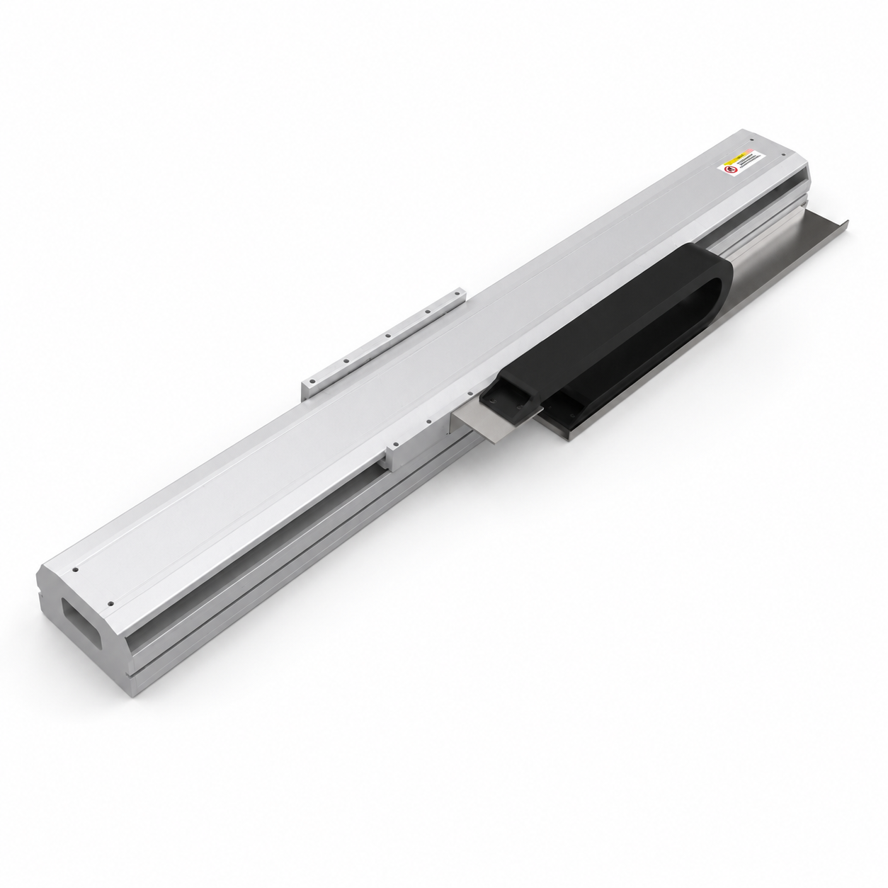
1 AC065 Model
Model
- AC065 ball-screw electric cylinder.
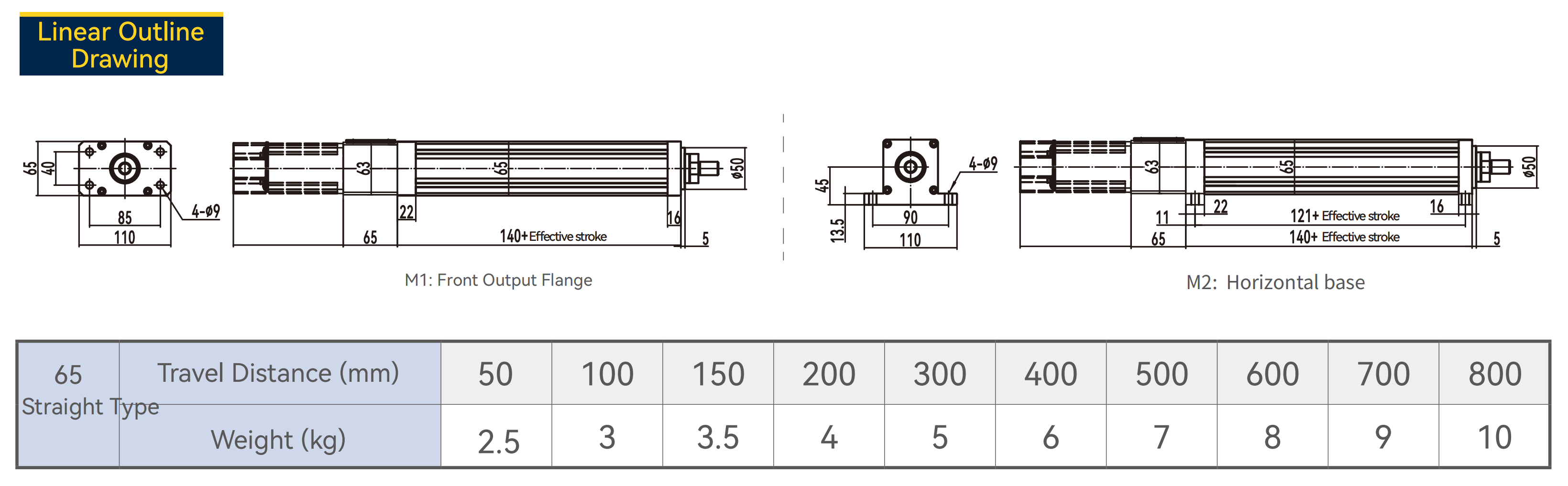
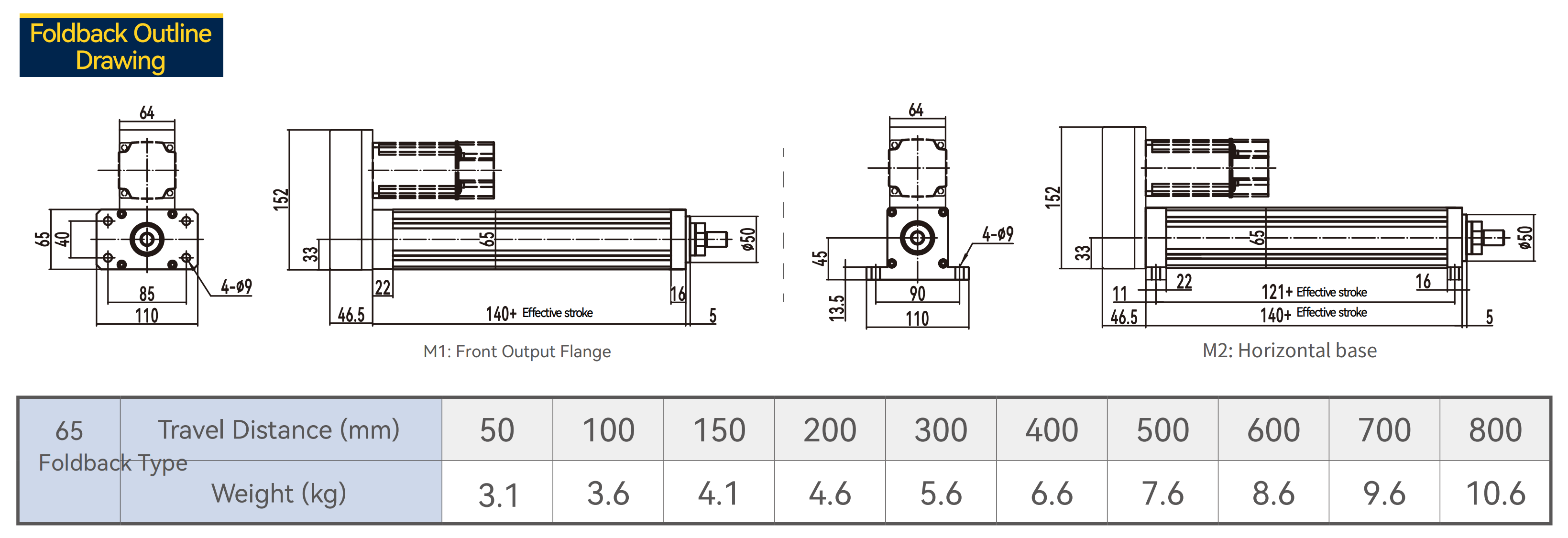
AC065 is a ball-screw electric cylinder for controlled push-pull, lifting and positioning motion. It supports straight or foldback motor layout and multiple installation and output connection options.
| Parameter | Specification |
|---|---|
| Maximum Stroke | 1200 mm |
| Stroke Range | 0–1200 mm |
| Stroke Pitch | 50 mm interval |
| Maximum Speed | 1000 mm/s |
| Rated Torque | 1.28 N·m |
| Max Thrust Bearing | 5 kN |
| Item | Specification |
|---|---|
| Drive Type | Ball-screw electric cylinder |
| Ball Screw | Ø16 mm |
| Lead Options | R5=5 mm / R10=10 mm / R20=20 mm |
| Body Size | 65 mm × 65 mm |
| Rod Anti-Rotation | T = anti-rotation / R = non-anti-rotation |
| Installation Method | M1 = front output flange / M2 = horizontal base / MX = user-defined |
| Output Connection | C1 external thread / C2 internal thread / C3 fish-eye bearing / C4 double trunnion / C5 single trunnion / C6 floating joint / CX user-defined |
| Accuracy Grade | P1 = C7 cold-rolled / P2 = C5 precision-ground |
| Motor Layout | S = straight / R = foldback |
| Drive Type Ball Screw | Motor Layout S / R | Lead Options R5 / R10 / R20 | Stroke Pitch 50 mm |
| Code | Layout | Selection Meaning |
|---|---|---|
| S | Straight-line type | Motor is arranged in line with the cylinder body for direct axial installation. |
| R | Foldback / turnback type | Motor is arranged in a folded layout to reduce overall length or fit limited installation space. |
| ENGINEERING NOTE | Final motor, reducer or coupling configuration should be confirmed according to thrust, speed, stroke, lead, duty cycle and installation space. |
| Item | Available Options | Selection Meaning |
|---|---|---|
| Installation Method | M1 / M2 / MX | M1 = front output flange; M2 = horizontal base; MX = user-defined. |
| Output Connection | C1 / C2 / C3 / C4 / C5 / C6 / CX | External thread, internal thread, fish-eye bearing, trunnion, floating joint or custom output. |
| Accuracy Grade | P1 / P2 | P1 = C7 cold-rolled ball screw; P2 = C5 precision-ground ball screw. |
| Sensor Requirement | Project-dependent | Confirm origin / limit sensor requirements according to controller input, stroke and safety logic. |